
Editor’s Note: This article follows “Causes and Remedies for Ductile Spool Component Failures” and “ASME Reviews Test Requirements for Pipes, Fittings, and Flanges.”
Traditional alloys play a standard role in the manufacture of metals, whether stainless steels for medical devices or marine products; all generations of high-performance steels developed over the past two decades for the automotive industry; or metals such as aluminum and titanium, which have high strength-to-weight ratios and high corrosion resistance, making them particularly suitable for aerospace, refining and chemical processing applications.
The same is true for some carbon steel alloys, especially those that contain specific amounts of carbon and manganese. Some of them, depending on the amounts of alloying elements, are well suited for the manufacture of flanges, fittings and pipes for chemical processing plants and refineries. All have one characteristic in common: the materials used in these applications must be sufficiently ductile to resist brittle fracture and stress corrosion cracking (SCC).
Standards organizations such as the American Society of Manufacturing Engineers (ASME) and ASTM Intl. (formerly known as the American Society of Testing and Materials) provide guidance on this. Two relevant industry codes—ASME Boiler and Pressure Vessel Code (BPVD) Section VIII, Division 1 and ASME B31.3, Industrial piping– consider carbon steels (any ferrous material containing 0.29% to 0.54% carbon and 0.60% to 1.65% manganese) as being sufficiently ductile to be used in hot climates, mild areas and areas where the temperature drops down to -20 degrees F. However, recent failures at ambient temperatures have led to closer scrutiny regarding the amounts and ratios of various microalloying elements used in the manufacture of these flanges, fittings and pipes.
Included or exempt?
Until recently, neither ASME nor ASTM required impact testing to confirm the ductile behavior of many carbon steel articles used at temperatures as low as -20 degrees F. Decisions to exempt some products were based on historical material properties. For example, carbon steel products such as A105 flanges, A234-WPB fittings, and A106 Class B carbon steel pipe with a wall thickness of ½” (25mm) or less, when used at a minimum design metal temperature (MDMT) of -20 degrees F, were exempt from impact testing due to their traditional role in such applications.
However, historical acceptance and mainstream applications do not necessarily hold forever. Some materials that fall under curve B of the 2017 revision of ASME VIII-1, UCS-66 (see Figure 1), have a recent documented history of failures due to brittle fracture at temperatures above -20 degrees F and, in many cases, hot temperatures. Therefore, they are considered to be at risk of brittle failure at room temperature, primarily during start-up, shutdown, hydrostatic testing, and rapid depressurization (autocooling).
The practice of voluntary additions of trace elements during the manufacture of medium-carbon steels, which contain 0.18% to 0.23% carbon, is possibly aimed at reducing the temperature and the heat treatment time. Used for decades, this technique has had an unintended consequence: brittle cracking of A105 grade flanges, A234-WPB fittings and A106-B carbon steel pipe. This phenomenon is known to occur at ambient temperatures.
This problem becomes acute when SCC-prone materials are deployed under certain service conditions. According to the National Association of Corrosion Engineers (NACE) MR0103, improper design, processing (cutting, bending, welding), installation, or handling can make resistant materials susceptible to SCC. Stress concentrations in local notches, such as corrosion pitting, make welds vulnerable to SCC. Residual tensile stresses from welding are also known to initiate cracking without external stresses. Welds that have not been released and components that have been cold worked are particularly vulnerable. Failure to meet the heat, mechanical or chemical treatment requirements of the specifications can only be verified by metallurgical examination. Imperfections on the machined surfaces of welded flanges can only be detected by non-destructive volumetric evaluation.
The EU has recognized this issue and is requiring impact testing at the relevant MDMT. ASME recognized this issue in the 2019 edition of the ASME BPVC VIII-I specification when it reassigned these carbon steels to Curve A of the impact test exemption curves shown in the illustration UCS- 66.
In the 2019 release, Curve A materials (rated for an MDMT of 18 degrees F) include the following:
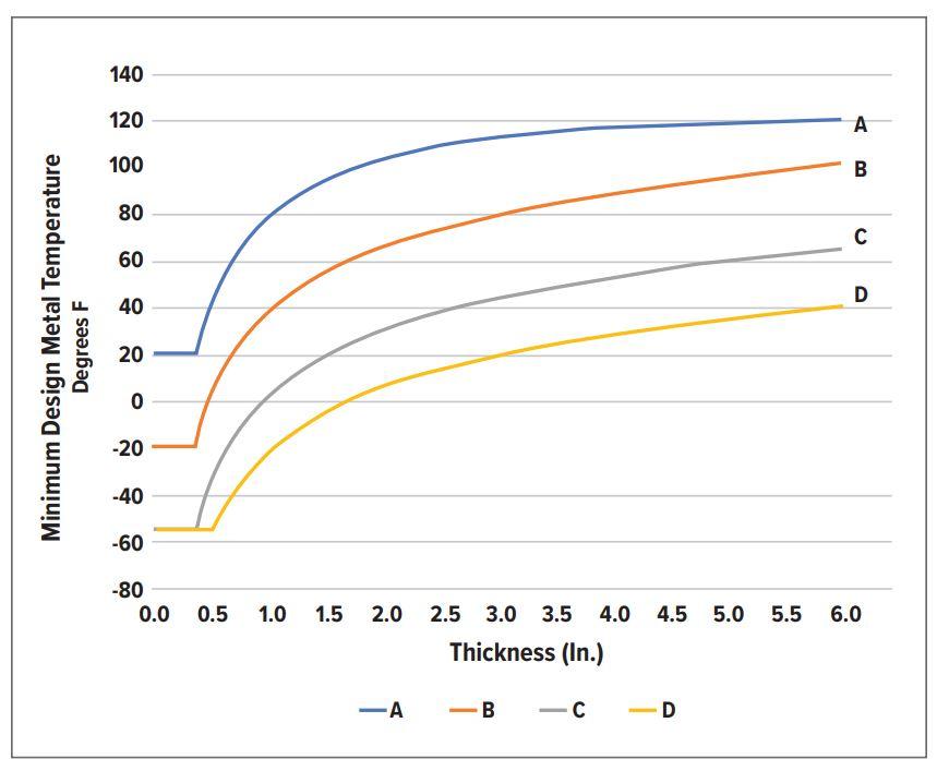
FIGURE 1. This graph, which approximates ASME UCS-66 and appears here for illustrative purposes only, shows four temperature functions for impact testing. If an alloy is listed as Curve C, its thickness is 3.5 inches and the MDMT is 60, it is above the curve and does not need an impact test. If a similar item has an MDMT of 40, it is below the curve and requires impact testing.
- A/SA-105 forged flanges delivered as-forged
- SA-216 WCB and WCC grades if normalized and tempered or water quenched and tempered
- SA-217 grade WC6 if normalized and tempered or water quenched and tempered
These steels can be returned to Curve B (-20 degrees F MDMT) with additional processing such as normalizing and tempering, listed in the notes of the UCS-66 illustration.
In the 2019 ASME BPVC Publication VIII-I, Illustration UCS-66, Curve B materials (rated for -20 degrees F MDMT) include the following:
- SA-105 Forged Flanges Produced Using Fine Grain Practice and Normalized, Normalized and Hardened, or Hardened and Hardened After Forging
- SA-216 grade WCA if normalized and tempered or water quenched and tempered
- SA-216 WCB and WCC grades for thicknesses not exceeding 2″ (50mm), if produced under fine grain practice and water quenched and tempered
Therefore, if impact testing is not possible, the manufacturer should use a more restrictive chemistry than the chemistry allowed by the control limits listed in the ASTM/ASME specifications of the individual materials to avoid brittle failure and SCC ( to see Figure 2).
The following notes provide additional information:
- Piping system product manufacturers have focused on the the amounts sulphur, phosphorus, manganese and carbon, in accordance with the relevant specifications, but the reports calcium to sulfur and manganese to carbon are also critical. The optimum calcium to sulfur ratio is about 2-1. The optimum manganese to carbon ratio greater than 5-1.
- According to API 571-2020, “microalloying elements like vanadium, niobium (formerly columbium, Cb), boron, and titanium in certain ranges, as well as sulfur, phosphorus, and manganese above their residual limits, may result in low toughness”. In these cases, microalloy means B
- At a minimum, thermal analyzes must comply with the applicable thermal analysis limits listed in Table 1 of ASME SA-20/20M.
- According to The Welding Institute, Cambridge, UK, rolled inclusions in steel provide planes of weakness which can lead to cracking problems due to weld shrinkage stresses (lamellar tearing) or hydrogen build-up at interfaces, which can lead to hydrogen-induced cracking. Calcium additions strengthen sulphide inclusions, reducing the extent of their deformation during rolling. This ensures uniformity of steel properties.
- Aluminum content greater than 0.02% or acid-soluble aluminum content greater than 0.015% per ASME SA-20, 8.3.2.1 and 8.3.2.2.
Without these precautions, carbon steel pressure-bearing components are likely to be vulnerable to brittle failure during hydraulic testing or during operation, even when operated at or below 60 degrees F.
Since the chemical composition of steel has been shown to be the primary cause of SCC failures, incorporating these best practices will go a long way toward reducing, and likely eliminating, this failure mode in piping systems. as described in ASME B31.3, B31.1, B31.12 and similar specifications.
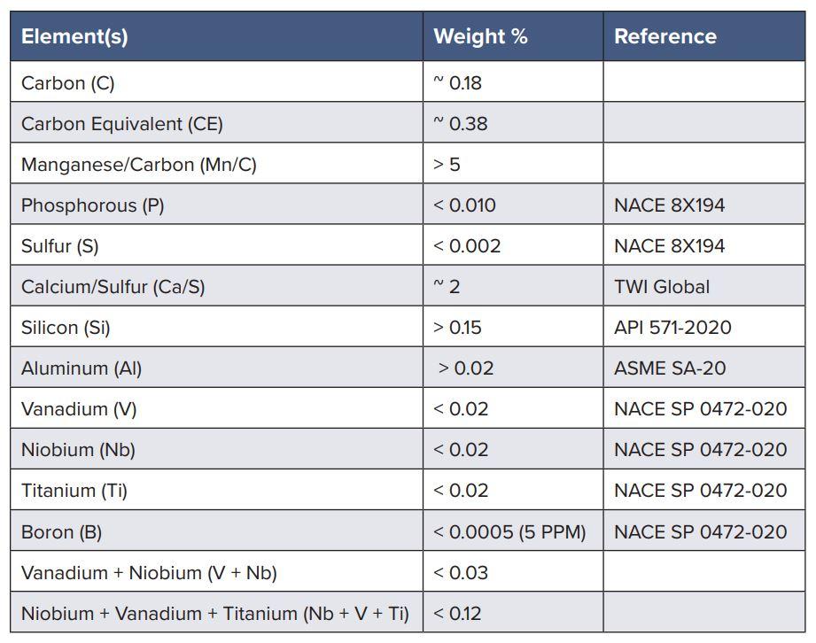
FIGURE 2. To prevent stress corrosion cracking in carbon steel, best practice includes the use of these steel chemistry control limits.